Understanding 2D Physics Engines with Phaser 3, Part 19: Clipping Method
- cedarcantab
- Jul 1, 2022
- 10 min read
Updated: Aug 20, 2023
Finding Contact Points of overlapping Convex Polygons using the Clipping Method

The separating axis theorem can tell us whether a polygon has overlapped with another polygon. It can also provide us with the minimum translation vector (MTV), comprising:
depth of penetration
collision normal.
With this information, we could:
resolve the penetration: "separate" the overlapping polygons by adjusting the position by the penetration depth, then
collision response: make them "respond" to the collision by providing them with some impulse along the collision normal in opposite direction.
Contact point generation
In a prior post we also looked at how we can "estimate" the contact point of two colliding rectangles. With a contact point we could make collision response more realistic by including rotational dynamics. In this point we look at the clipping method which can generate high quality contact point(s) for arbitrary convex polygons.
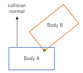
Consider the below situation of the red box falling onto the blue box from above. Based on my implementation of SAT to date, the collision normal would point vertically upwards, and the estimated contact point would be as shown in green.
Multiple contact points
A contact point describes a point at which two objects touch. Conceptually easy enough to understand. However, consider the below situation. The rectangles are touching along the edge, as opposed to a single point, ie there are a infinite number of contact points.

For the purposes of our simple physics engine in 2D, we only need two contact points in order to generate reasonably realistic looking collision response - but how to identify those two points along the overlapping edge?
One robust method is called the clipping method which is a popular method for generating good quality contact points for any pair of convex polygons.
Clipping Method
The basic steps are:
Identify the colliding features (i.e. the edges, in 2D), sometimes referred to s the significant faces
Of the colliding edges, identify the "reference edge" and the "incident edge"
"Clip" the incident edge against the "adjacent faces" of the reference edge
"Clip" the incident edge against the reference edge itself
I am pretty certain the above makes no sense, so will go through each step in detail with examples...but before we get to the clipping methods, we introduce a few new objects.
Edge Feature Object
The method operates on "edges" of the polygons. As such I have created a new object to hold the information about a particular edge called EdgeFeature, for ease of readability.
class EdgeFeature {

	constructor(vertex1, vertex2, index) {

	  // make sure that when instantiated, it is right winding
	  this.vertex1 = vertex1; // pointfeature
	  this.vertex2 = vertex2; // pointfeature

	  this.edge = vec2.normalize(new vec2(), new vec2(vertex2.getPoint().x - vertex1.getPoint().x, vertex2.getPoint().y - vertex1.getPoint().y));

	  this.normal = new vec2(this.edge.y, -this.edge.x); // outward facing normal

	  this.index = index;
	}

	getVertex1() {
		return this.vertex1;
	}

	getVertex2() {
		return this.vertex2;
	}

	getEdge() {
		return this.edge;
	}

	getMaximum() {
		return this.max;
	}

}
A new EdgeFeature object is instantiated with its two end points (Vector2's). At instantiation it will create the following properties:
this.edge: a unit vector pointing from v1 to v2
this.normal: a unit vector perpendicular to the edge
Manifold Object
As suggested above this method will produce up to 2 contact points. We extend the Manifold object so hold an array of contact points.
class ContactConstraint {

	constructor(body1, body2, penetration) {

	  this.body1 = body1;
	  this.body2 = body2;

	  this.normal = new vec2(penetration.normal.x, penetration.normal.y);
	  this.depth =  penetration.depth;

	  this.contacts = [];
	  this.numContacts;

	  this.restitution = Math.min(body1.restitution, body2.restitution)
	  this.friction = Math.sqrt(body1.friction * body2.friction);

	  this.beta = 0.2;

	}

  }
The property this.contacts will hold the actual contact points.
Winding order
And also a reminder about the winding order of an object.
Consider you have a polygon. You start by picking any vertex. Then you can pick the other vertices from your point of view in either clockwise or counter-clockwise order. The way you do this is called the winding order.
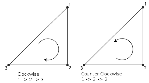
To effectively implement the clipping method, you need to be consistent in your winding order when you construct your polygons.
In my implementation, I have assumed a right handed coordinate system (ie x-axis pointing to the right, y-axis up, z-axis pointing out from the screen towards you) and a CCW winding order.
Identify Colliding Features
First step is to identify the colliding features, i.e. the edges that are intersecting.
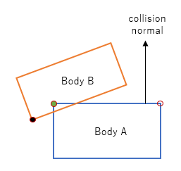
Note that SAT has just been completed and detected overlap between body A and body B, with the collision normal pointing from body A to body B.
We start by first selecting the vertex that is farthest along the collision normal. It may seem to be counter-intuitive to look for farthest vertices in identifying the colliding edges, ie the edges that are closest. However it will become clearer by looking at an actual example, below.
Search for the vertex of body A along the collision normal would result in the green highlighted vertex (it could just well as be the empty circle vertex - depends on the order in which the vertices are searched - does not matter which one is selected)
Search for the vertex of body B along the opposite direction of the collision normal - this would result in the black highlighted vertex.
Getting the farthest vertex along an axis
Getting the farthest vertex along a particular direction is relatively easy. You simply loop through all the vertices and take the vertex with the largest dot product against the direction vector.
Since I am using Geom.Polygon which holds its vertices as Geom.Point objects, I have created the relevant methods to find the farthest vertex by extending the Geom.Point class.
    getFarthestPoint(  d ) {

        // find the index of the farthest point
        var index = this.getFarthestVertexIndex(d);

        return this.vertices[index];

    }

    getFarthestVertexIndex(d) {

        let bestProjection = Number.NEGATIVE_INFINITY;

        let maxIndex = 0;

        for (let i = 0; i < this.vertices.length; ++i)		{

            const v = this.vertices[i];
            const projection = vec2.dot(v, d);
            if (projection > bestProjection) {
                maxIndex = i;
                bestProjection = projection;
            }

        }

        return maxIndex;

    }
Then the edges (referred to as features or faces) meeting the following conditions are identified:
edge includes the selected vertex
the edge's normal is the closest to parallel with the collision normal of all edges which contain the selected vertex
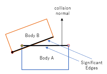
Specifically, given that we know the relevant vertex, we simply check the edge that lies to the "left" and then the edge to the "right" of the vertex, comparing the dot product against the collision normal.
The following method has been added to the Polygon class to implement the above. Given a vector n, this method will return the farthest 'feature' (ie edge) as an EdgeFeature object.
   getFarthestFeature(n) {

        var index = this.getFarthestVertexIndex( n);
        var count = this.vertices.length;

        var maximum = this.vertices[index];
        var vm = new PointFeature(maximum, index);

        // get the vertex to the "left" of the maximum vertex
        var l = (index == count - 1) ? 0 : index + 1;
        var left = this.vertices[l];
        var leftN = this.normals[l]

        // get the vertex to the "right" of the maximum vertex
        var r = (index == 0) ? count - 1 : index - 1;
        var right = this.vertices[r];
        var rightN = this.normals[index]

        // the edge that is most perpendicular to n will have a dot product closer to zero
        if (Math.abs(vec2.dot(leftN, n)) <= Math.abs(vec2.dot(rightN, n))) {
            // the left edge is better. make sure to retain the winding direction
            var vl = new PointFeature(left, l)

            return new EdgeFeature( vm, vl, index+1);

        } else {
            // the right edge is better. make sure to retain the winding direction
            var vr = new PointFeature(right, r)
            return new EdgeFeature( vr, vm, index);
        }

    }
Identify Reference Edge vs Incident Edge
The reference edge will become the point of reference when clipping occurs in subsequent steps. The incident face will in turn become a set of vertices that will be clipped.
Of the two significant faces, the reference edge will be the one that is most perpendicular when compared against the collision normal. The "other" edge shall be the incident edge.

Testing for the edge that is more perpendicular to the collision normal is simply comparing the dot product of the respective edges against the collision normal.
class ClippingSolver {


    static getContact(boxA, boxB, manifold) {

      // get the penetration normal
      var n = manifold.normal;

      // get the reference feature for the first convex shape
      var feature1 = boxA.getFarthestFeature(n);
      // check for vertex
      if (feature1 instanceof PointFeature) {

        manifold.contacts.push(new Contact(feature1));
        manifold.numContacts = manifold.contacts.length;
        return true;
      }
      // get the opposit of the collision normal - assume normal is already a unit vector
      var ne = vec2.negate(new vec2(), manifold.normal);
      // get the reference feature for the second convex shape
      var feature2 = boxB.getFarthestFeature(ne);
      // check for vertex

      if (feature2 instanceof PointFeature) {

        manifold.contacts.push(new Contact(feature2));
        manifold.numContacts = manifold.contacts.length;
        return true;
      }

      // of the reference features, identify which is the incident edge and the reference edge
      var e1 = feature1.getEdge();
      var e2 = feature2.getEdge();

      var ref, inc;

      if (Math.abs(vec2.dot(e1, n)) <= Math.abs(vec2.dot(e2, n))) {
        ref = feature1;
        inc = feature2;
      } else {
        ref = feature2;
        inc = feature1;
      }
Clip Incident Edge against the adjacent face of the Reference Edge
Now we have the two edges involved in the collision, we clip the incident edge against the adjacent "faces" of the reference edge.
First clip
First, we clip the incident edge by the "face" or "plane" adjacent to the vertex on the "left" of the reference edge. Conceptually we check both vertices of the incident edge, see which "side" of the adjacent "face" they lie, then if the vertex is on the "wrong side" of the face, we clip it and replace it with the point of intersection between the incident edge and the reference edge - in the diagram below, that is c2.
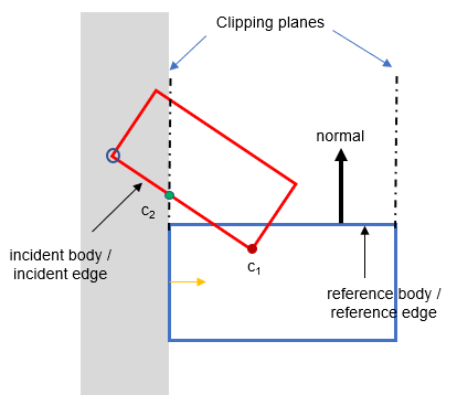
There are two sub-topics to what I have described above. Namely:
how do determine which side of a line a point lies
how to find the intersection point
Determining which side of a line a point lie
I (and you will find that other people writing about this subject) make references to "edge", "face", "plane", "side" etc. which may be confusing. It may seem a bit of detour but in discussing this topic of how one might determine which side of a line a point lie, it is useful to define the clipping edge/face/line (i.e. the dotted line in the diagram above) as a plane - think of a thin plate slicing through your PC screen vertically.
A plane can be expressed by means of (i) one point on the plane P, and (ii) a normal vector pointing "outwards" perpendicularly from the plane. More specifically, all points X on such a plane can be expressed in the constant-normal form as n・X=d, where d = n・P.
In the diagram above, the reference edge itself is the normal (you need to be careful about the direction), and the relevant vertex of the reference edge would be the "one point" P on the plane.
I will not derive it here, but it can be shown that if the normal of the plane is n, and the one identifying point on the plane is P, and the point you are evaluating is A, then t=n・(A-P) = n・A - n・P = n・A - d will give you the "signed distance" of A from the plane.
In the above diagram, we can test the vertex circled in blue against the plane on the left hand side defined by the yellow colored normal. It is on the negative side so it needs to be clipped and replaced with the green highlighted point, i.e. the intersection between the incident edge and the clipping plane.
Determining the intersection of an edge against a plane
Again, I will not elaborate on the derivation but the intersection point Q between a plane expressed as n・X=d, where d = n・P, and a line segment defined by the end points A and B can be found by:
Q = A + [(d- n・A)/(n・(B-A))](B-A) = A + [( n・A-d)/(n・A - n・B)](B-A)The above can be implemented as follows.
First, the d = n・P in the above equation of a plane is calculated by taking the dot product between the reference edge (ie the normal of the plane) with the relevant end vertex of the reference edge. Then the clip method is called with:
inc.v1, inc.v2 - the end-points of the edge to clipped
ref.edge, o1 - the elements that define the clipping plane
     var refev = ref.getEdge();

      // compute the offset of the reference edge points along the reference edge
      var offset1 = vec2.dot(refev, ref.getVertex1().getPoint());

      // clip the incident edge by the reference edge's left edge
      var clip1 = ClippingSolver.clip(inc.getVertex1(), inc.getVertex2(), ref.edge, offset1);

      // check the number of points
      if (clip1.length < 2) {
        return false;
      }
The actual clip method is as follows.
  static clip(v1, v2, n, d) {

      if (!(v1 instanceof PointFeature) || !(v2 instanceof PointFeature) )    {

        console.log("TYPE ERROR! v1=",v1,"v2=",v2)

      }

      var a = v1.getPoint();
      var b = v2.getPoint();

      var cp = [];

      var d1 = vec2.dot(n, a) - d;
      var d2 = vec2.dot(n, b) - d;

      if (d1 > 0) cp.push(v1);
      if (d2 > 0) cp.push(v2);
      if (d1 * d2 < 0) {
        var e = vec2.subtract(new vec2(), b, a);
        var u = d1 / (d1 - d2);
        vec2.scaleAndAdd(e, a, e, u);
        cp.push(new PointFeature(e))
      }
      return cp;
    }
In the red highlighted code, d1, and d2 are calculating the signed distance of the end-points of the incident edge (passed as a and b).
In the blue highlighted code, the vertices on the "positive" side of the clipping plane is pushed into the cp array for safe keeping (ie points that are on the negative side are discarded).
The meaning of green highlighted code is:
if the vertices a and b lie on opposite side of the clipping plane,
calculate the point of intersection between the clipping plane and the line segment
push the calculated intersected point into the cp array
Second clip
The clipping operation is then repeated against the other adjacent plane of the reference edge. In this particular case, the vertices are on the positive side of the clipping plane so they are not clipped. The clipped points c1 and c2 are forwarded to the next stage.
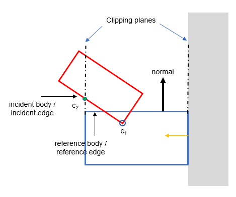
The code for this is as follows. It is very similar to the code for the first clipping operation, except:
the normal of the clipping plane must be facing the opposite to the first clipping plane
the points to be clipped are not the end-points of the original incident edge, but what's left of the first clipping operation
   // compute the offset of the reference edge points along the reference edge
      var offset2 = -vec2.dot(refev, ref.getVertex2().getPoint());

      // clip the clip1 edge by the reference edge's right edge
      var clip2 = ClippingSolver.clip(clip1[0], clip1[1], vec2.negate(new vec2(), vec2.clone(refev)), offset2);
      // check the number of points

      if (clip2.length < 2) {
        return false;
      }
Clip Incident Edge against the Reference Edge itself
The final clipping operation is against the reference edge itself. This time, any points "inside" (i.e. positive side of the clipping plane as defined by the outward collision normal in the above diagram) of the clipping region are removed.
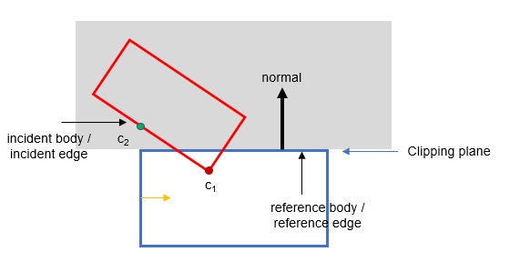
In the above diagram, point c2 is removed, leaving c1 as the one contact point.
This is implemented as follows. The logic for deciding which points should be removed is the same as that of the previous clipping operations.
  // finally, clip against the reference edge itself
      var refNorm = ref.normal;

      var max = vec2.dot(refNorm, ref.getVertex1().getPoint());

      // make sure the final points are not past this maximum
      for (let i = 0; i < clip2.length; i++) {
        var vertex = clip2[i];
        var point = vertex.getPoint();
        if (vec2.dot(refNorm, point) - max <= 0) {
          manifold.contacts.push(new Contact(clip2[i]));
        }
      }

      manifold.numContacts = manifold.contacts.length;

      return true;

    }
The number of contact points is stored in the manifold property numContacts.
And the operation is complete.
Sample Code
Useful References
https://dyn4j.org/2011/11/contact-points-using-clipping/ (this explains step by step how to implement contact points using clipping, in Java)
https://gdcvault.com/play/1015496/Physics-for-Game (for the very advanced! Talks about multiple contacts points with rotation)
https://box2d.org/files/ErinCatto_ContactManifolds_GDC2007.pdf (this explains the key points of contact generation, with reference to SAT and GJK)
https://www.toptal.com/game/video-game-physics-part-ii-collision-detection-for-solid-objects (this covers a lot of topics and is a good read to get overall understanding of context)
http://media.steampowered.com/apps/valve/2015/DirkGregorius_Contacts.pdf (this is quite beginner friendly - goes into a fair bit of depth about different situations of contact points)
http://www.richardtonge.com/presentations/Tonge-2012-GDC-solvingRigidBodyContacts.pdf (a little bit more detail)
https://research.ncl.ac.uk/game/mastersdegree/gametechnologies/previousinformation/physics5collisionmanifolds/2017%20Tutorial%205%20-%20Collision%20Manifolds.pdf (describes clipping method)
Series of beginner friendly tutorials for based on a different but intuitively easier to understand contact generation method
https://youtu.be/aIgxC2oJIwc (introduction to collision manifold)
https://youtu.be/LNr-0lMH1ok (circle to circle)
https://youtu.be/V2JI_P9bvik (circle to polygon)
https://youtu.be/5gDC1GU3Ivg (polygon to polygon)


Comments