Understanding 2D Physics Engines with Phaser 3, Part 6: Rectangle Collision Detection & Resolution
- cedarcantab
- Mar 7, 2022
- 9 min read
Updated: May 11, 2023
Axis Aligned Rectangle Collision Detection and Resolution
Having worked through the logic of collision detection between circles and lines, I now turn my attention rectangles, specifically axis-aligned, or unrotated rectangles in 2 dimensions (I will refer to them as axis aligned bounding boxes or AABB, for the rest of this post).
In some respects, the principles associated with AABB's are simpler than for circles, but with anything in the world of physics engines, there are lots of subtleties in the implementation, some of which I will try to touch on.
Once again, I will be taking a peek at many of Phaser's built-in classes and methods relevant to this for our study. As well as the various geometry methods, Phaser's very efficient arcade physics engine adopts AABB (in addition circle) as the shape of the physics body, this will provide us a lot of insight.

Defining an AABB
To start with the most basic assumption. In this post we are only dealing with rectangles or boxes whose edges are aligned with the coordinates axes.
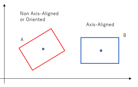
In Phaser, the Geom.Rectangle class is defined with (x,y) being the top-left hand corner, width (extending to the right) and height (extend to bottom).
Customized Box class
I have created a custom "Box" class by extending Phaser.Geom.Rectangle, with the constructor function is as follows.
class Box extends Phaser.Geom.Rectangle {
  constructor(scene, x, y, width, height) {
    super(x - width/2, y - height/2, width, height);
    this.scene = scene;
    this.type = "box";
    this.halfWidth = width/2;
    this.halfHeight = height/2;
    // linear components
Position reconfigured to be center of box as opposed to top left
You will note that I have "converted" the (x, y) to be the "centre" of the rectangle, and added the properties, halfWidth and halfHeight. This was done to more easily follow through from the thinking applied to circles, ie half-width and half-height instead of a radius, measured from the center point.
Also remember that the Phaser's rectangle class has the following properties:
left, right, top, bottom
width, height
With the extended set of properties to define the box, we can explore the various ways of detecting intersection.
Detecting intersections
There are many different ways of detecting intersections, ie collision.
Look at the distance between the centers
In detecting intersection between circles, we compared:
the distance between the centers of the cirlces,
the sum of the radii,
and noted that if (1) was less than (2), there must be intersection.
We can take a similar logic for rectangle vs rectangle.
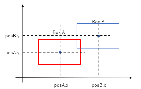
By looking at the above diagram, the distance between the centers along the x-axis (posB.x - posA.x) is less than the sum of the half widths (equivalent to the sum of the radii, in our circles analogy). Hence we can say that along the x-axis, the rectangles overlap.
The intersection is not finished however. You need to do the same test along the y-axis. In the above situation, (posB.y - posA.y) is less than the sum of the half height of the two rectangles. Hence we can say that the rectangles overlap along the y-axis, as well as the x-axis.
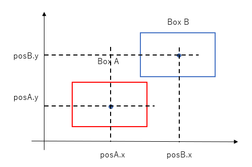
The need to carry out the intersection test along both the x-axis and the y-axis should be clear if you look at the diagram below, the test along the x-axis will yield a positive result but the test along the y-axis will yield a negative result.
To summarise, there is overlap if:
the x-distance between the centers of the two rectangles is less than the sum of their half-widths, there is overlap, AND
the y-distance between the centers of the two rectangles is less than the sum of their half-heights.
Projecting the rectangles onto the x- and y-axes
Another way of looking at intersections involves the concept of projection. One can think of this concept as shining a light against the rectangle and looking for the shadow on the respective axes. So for the following situation, the projection of the red rectangle along the x-axis is simply (right - left) or (max.x - min.x) and projection along the y-axis is (top - bottom) or (max.y - min.y). These shadows are commonly referred to as intervals.
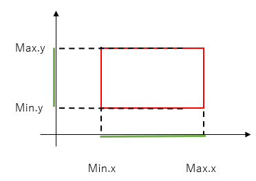
In the case of axis-aligned rectangle, this is overly complicated way of saying, look for the left, right, top and bottom. However, this concept of projection will become critically important to understand when we come to analyze intersections between oriented geometries.
Looking for overlap between the intervals
By looking at the below diagram which shows the projection of boxA and boxB along the x- and y-axes, it should be clear that the two boxes intersect if:
the intervals (the projections of the respective boxes) along the x-axis overlap; AND
the intervals along the y-axis overlap
But how do we actually assess whether intervals overlap?
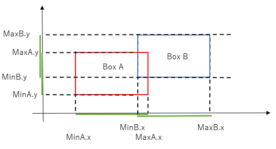
Looking at the above diagram, it should be clear that the intervals along the x-axis overlap because minB.x < maxA.x, ie the left edge of box B (which lies to the right of box A) is to the left of the right edge of box A. This condition can be expressed as several different boolean expressions,
minB.x < maxA.x,
minB.x - maxA.x < 0
maxA.x - minB.x > 0
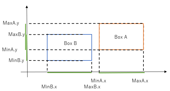
What if box A is positioned to the right of box B (ie the opposite of the above)? Looking at the situation below, the above booleans will yield true, ie indicate there is overlap.
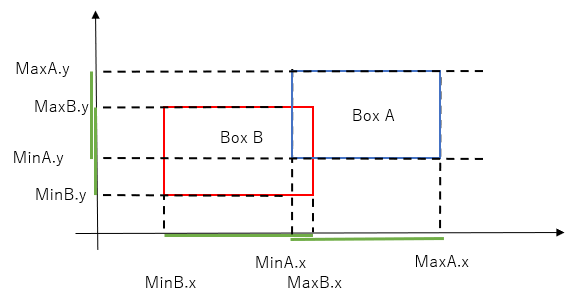
However, the same boolean expression will yield true in the below situation too - clearly not the correct result. In the above diagram, the appropriate boolean expressions are:
minA.x < maxB.x, or
minA.x - maxB.x < 0, or
maxB.x - minA.x > 0
It is useful to note that (maxB.x - minA.x) gives you the depth of overlap if positive, or the separated distance if negative - we will come back to why this useful, later on.
In otherwords, the tests are different depending on the relative position of the two rectangles. To summarise, intervals along the x-axis overlap if:
if box B is to the right of box A, check maxA.x - minB.x > 0
if box A is to the right of box B, check maxB.x - minA.x > 0
We could code the above as a conditional statement (for both the x- and y-axes projections); that would work fine.
Looking for the depth of overlap
To find the depth of overlap:
if box B is to the right of box A, depth of overlap = maxA.x - minB.x
if box A is to the right of box B, depth of overlap = maxB.x - minA.x
Let us also note that:
In case 1 above, maxA.x < maxB.x and minA.x < minB.x
In case 2 above, maxA.x > maxB.x and minA.x > minB.x
From the above, we can calculate the depth of overlap with the following one line:
Math.min(maxA.x, maxB.x) - Math.max(minA.x, minB.x)Hence, we can detect overlap by:
Math.min(maxA.x, maxB.x) - Math.max(minA.x, minB.x) > 0 &&
Math.min(maxA.y, maxB.y) - Math.max(minA.y, minB.y) > 0
Detecting rectangles do NOT overlap
Let's look at conditions for rectangles that do NOT overlap, ie separated.
We can see from the below diagram that rectangles do not intersect if either:
the intervals (the projections of the respective boxes) along the x-axis do NOT overlap; OR
the intervals along the y-axis do NOT overlap
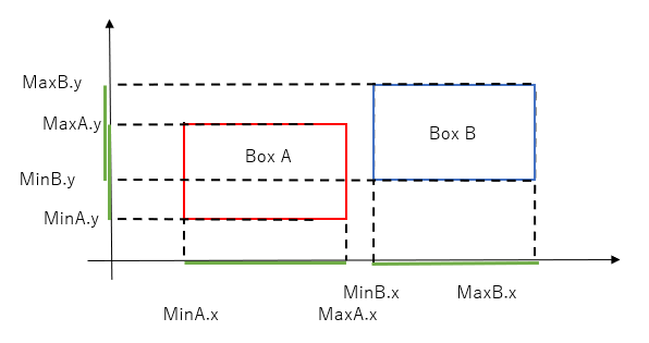
And how do we determine whether intervals are separated? Looking at the diagram above, we can see that intervals along the x-axis do not overlap because minB.x > maxA.x (ie the left edge of box B - which is on the right of box A - is to the right of the right edge of box A.
We also need to account for situation where box A is to the right of box B ('opposite' to the situation above). In this case, the intervals along the x-axis does not overlap because minA > maxB.
In otherwords, the intervals along the x-axis do NOT overlap if:
minB.x > maxA.x OR minA.x > maxB.x 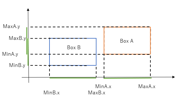
We also need to do the same test for the intervals along the y-axis.
Putting it all together, we can say that the rectangles are separated (do not overlap) if:
minB.x > maxA.x OR minA.x > maxB.x , OR
minB.y > maxA.y OR minA.y > maxB.y
Phaser provides several methods for checking intersection between two axis aligned rectangles
Phaser provides several public methods for checking for intersection between two axis aligned rectangles:
Geom.Intersects.RectangleToRectangle
Geom.Intersects.GetRectangleToRetangle
<static> RectangleToRectangle(rectA, rectB)
The relevant bit is actually just the red highlighted code. The logic is straighforward. It is returning the negative of the condition that the rectangles do NOT overlap. And the logic for checking that there is NO overlap is the same as the interval projection approach described above.
var RectangleToRectangle = function (rectA, rectB)
{
    if (rectA.width <= 0 || rectA.height <= 0 || rectB.width <= 0 || rectB.height <= 0)
    {
        return false;
    }

    return !(rectA.right < rectB.x || rectA.bottom < rectB.y || rectA.x > rectB.right || rectA.y > rectB.bottom);
};
There is another method for detecting intersections between two rectangles by the Phaser.Geom.Intersects class.
GetRectangleToRectangle(rectA, rectB [, out])
This is a method that returns all the intersection points of the two rectangles. Interestingly, what it does it to call GetLineToRectangle method between each of the 4 boundaries of rectangle A, vs rectangle B. GetLineToRectangle, in turn actually calls GetLineToLine for comparing the line against the four boundaries of the rectangle.
GetLineToLine does not restrict checking to axis aligned lines. The algorithm in theory would cope with non-axis aligned rectangles, if it were not for the fact that the Geom.Rectangle class can only be used to define axis aligned rectangles.
var GetRectangleToRectangle = function (rectA, rectB, out)
{
    if (out === undefined) { out = []; }

    if (RectangleToRectangle(rectA, rectB))
    {
        var lineA = rectA.getLineA();
        var lineB = rectA.getLineB();
        var lineC = rectA.getLineC();
        var lineD = rectA.getLineD();

        GetLineToRectangle(lineA, rectB, out);
        GetLineToRectangle(lineB, rectB, out);
        GetLineToRectangle(lineC, rectB, out);
        GetLineToRectangle(lineD, rectB, out);
    }

    return out;
};
By comparing intersection between bounding edges, you get more information like the actual intersection points.
Collision resolution
Unlike circles, where I will push the rectangles apart along one axis, the relevant axis being the axis with the least amount of overlap.
It is easier to look at the actual code, which is significantly easier than that of the circle2circle collision resolution.
 resolveRectangleToRectangle(rectA, rectB) {
    let separation = new Phaser.Math.Vector2();
    let resolution = new Phaser.Math.Vector2();
    const dx = rectA.position.x - rectB.position.x;
    const dy = rectA.position.y - rectB.position.y;
    let sx = (rectA.halfWidth + rectB.halfWidth) - Math.abs(dx);
    let sy = (rectA.halfHeight + rectB.halfHeight) - Math.abs(dy);
    if (sx < sy) {
      resolution.set(dx > 0 ? sx/2 : -sx/2,0)
    } else {
      resolution.set(0, dy > 0 ? sy/2 : -sy/2)
    }
    rectA.position.add(resolution);
    rectB.position.add(resolution.negate());
  }
How does Phaser's arcade physics engine detect and separate rectangles?
As an aside, how does Phaser's arcade physics engine check for intersection between rectangles (the default shape of physics body)?
The actual code is long and complicated because, among other things, the need to deal with different shapes, but the key bit relating to rectangles is part of the separate method.
separate(body1, body2, processCallback, callbackContext, overlapOnly, intersects)
It looks like Phaser is also, in principle only moving the rectangle along one axis, unless one axis separation in itself doesn't eliminate the collision entirely (what kind of situation would that be?). I don't fully understand the logic for determining which axis to separate along first, but it seems to be dependent on:
forrceX property being set to true (this is the default), OR
the gravity along the y direction is smaller than the gravity in the x-direction
var resultX = false;
var resultY = false;

//  Do we separate on x first or y first or both?
if (overlapOnly)
        {
            //  No separation but we need to calculate overlapX, overlapY, etc.
            resultX = SeparateX(body1, body2, overlapOnly, this.OVERLAP_BIAS);
            resultY = SeparateY(body1, body2, overlapOnly, this.OVERLAP_BIAS);
        }
        else if (this.forceX || Math.abs(this.gravity.y + body1.gravity.y) < Math.abs(this.gravity.x + body1.gravity.x))
        {
            resultX = SeparateX(body1, body2, overlapOnly, this.OVERLAP_BIAS);

            //  Are they still intersecting? Let's do the other axis then
            if (this.intersects(body1, body2))
            {
                resultY = SeparateY(body1, body2, overlapOnly, this.OVERLAP_BIAS);
            }
        }
        else
        {
            resultY = SeparateY(body1, body2, overlapOnly, this.OVERLAP_BIAS);

            //  Are they still intersecting? Let's do the other axis then
            if (this.intersects(body1, body2))
            {
                resultX = SeparateX(body1, body2, overlapOnly, this.OVERLAP_BIAS);
            }
        }

        var result = (resultX || resultY);

        if (result)
        {
            if (overlapOnly)
            {
                if (body1.onOverlap || body2.onOverlap)
                {
                    this.emit(Events.OVERLAP, body1.gameObject, body2.gameObject, body1, body2);
                }
            }
            else if (body1.onCollide || body2.onCollide)
            {
                this.emit(Events.COLLIDE, body1.gameObject, body2.gameObject, body1, body2);
            }
        }

        return result;
    },
The actual bit dealing with the separation is SeparateX method, which in turn calls another method called GetOverlap(body1, body2, overlapOnly, bias). This method is very long as it deals with different physics body properties, but the key bit is reproduced below, with the complicated bits reducted.
{
    var overlap = 0;
    var maxOverlap = body1.deltaAbsX() + body2.deltaAbsX() + bias;

    if (body1._dx === 0 && body2._dx === 0)
    {
        //  They overlap but neither of them are moving
        body1.embedded = true;
        body2.embedded = true;
    }
    else if (body1._dx > body2._dx)
    {
        //  Body1 is moving right and / or Body2 is moving left
        overlap = body1.right - body2.x;

   // REDUCTED //

    else if (body1._dx < body2._dx)
    {
        //  Body1 is moving left and/or Body2 is moving right
        overlap = body1.x - body2.width - body2.x;

        if ((-overlap > maxOverlap && !overlapOnly) || body1.checkCollision.left === false || body2.checkCollision.right === false)
        {
            overlap = 0;
        }
        else

  //REDUCTED //

    //  Resets the overlapX to zero if there is no overlap, or to the actual pixel value if there is
    body1.overlapX = overlap;
    body2.overlapX = overlap;

    return overlap;
};
Sample Code
Below is a simple example which:
uses the Geom.Intersects.RectangleToRectangle to detect overlaps
resolveRectangleToRectangle method explained above to apply impulse to separate the colliding rectangles


Comments