Space Invaders in Phaser 3 (Part 0): The Beginning
- cedarcantab
- Jan 9, 2022
- 6 min read
Updated: Jan 16, 2022
I have worked on the Danmaku project pretty much non-stop for several months. Whilst there are plenty more that I want to do, I have started a different project; one that involves completing a playable game and in so doing learning the key logic involved in creating such games. Specifically I have been working on creating the classic Space Invaders game using Phaser 3 framework over the last couple of weeks.
I started learning Javascript in the summer of last year, and the fact that I have now got a playable game speaks volumes about the power of Phaser 3.
Along the way, I relied on a lot of tutorials available for free on the internet and I have learned a lot along the way. I thought I would write some of those learnings in this multi-part series so that other people starting out (like me half a year ago) might find it helpful.
However, I will also say that I took quite a lot of detours trying to understand how the original code worked. A lot of which in hindsight was totally irrelevant as far as achieving the same effect on modern day computers using Javascript/Phaser is concerned. A lot of the stuff which took many instructions in machine code/assembly language to achieve on the hardware of those days can be achieved with just a few lines of code. However, I personally found it interesting to imagine the challenges that were involved in creating one of the best-ever selling games that was hailed as revolutionary. As I will document such "detours" into 8080 assembly language code, my "tutorials" will be a bit different from the more usual "how-to-write your first game in Phaser" type of tutorial!
In anycase, I would love to get feedback my code as I am sure there's much better ways to write the code, and indeed any of my writings in the upcoming posts.
During my fumblings to write my own Javascript version, I have relied on many sources of information, particularly below:
The original arcade game ran on the "Midway 8080 hardware", which as the name suggests used a CPU called 8080, which was developed by Intel. The remarkable Computer Archeology ("CA") site above provides pretty much a fully commented disassembly of the original code. However, as I cannot read 8080 assembly language, I did at times refer to the Emulator 101 site sometimes to give me a little bit more insight where CA did not offer commentary for a total beginner like me.
Original hardware
As a flavour of the fascinating nature of exploring the original hardware, here's a little bit about how "video" worked.
The Midway 8080 architecture generates video from a black-and-white frame-buffer, using apparently 7KB of RAM! That's kilobytes! not mega-bytes! In fact, the entire memory map was as follows:
Start End Description
$0000 $1FFF ROM
$2000 $23FF General-purpose RAM
$2400 $3FFF Video frame buffer RAM
The video frame had 256 horizontal by 224 vertical pixels (as I will come back to later, the screen was "rotated" by 90 degrees anti-clockwise, to "portrait" mode). Each byte (=8 bits) corresponds to 8 pixels. Each "bit"=pixel can be 1 or 0 representing whether it is white or dark. There are 32 bytes per "scanline", hence 32x8 = 256 pixels across (when not rotated).
CA has the following diagram is useful to understand what this means.
2400 - 3FFF (1C00 bytes = 256 * 28) 28*8=224. Screen is 256x224 pixels.

The map below shows the raster layout. Take this map and rotate it counter clockwise once. Thus the first byte is lower left. First "row" ends upper left. Last byte is upper right.

     2400     2401     2402        ....   241F
     01234567 01234567 01234567    ....   01234567

     2420     2421     2422        ....   243F
     01234567 01234567 01234567    ....   01234567

     .                                    .
     .                                    .
     .                                    .
     .                                    .

     3FE0     3FE1     3FE2        ....   3FFF
     01234567 01234567 01234567    ....   01234567
In essence the video buffer can be thought of a 224 x 32 byte array. Looking at the above image, you can imagine writing a horizontal (in the original, unrotated screen) line of 8 pixels at the top left hand corner of the screen by writing FF to address $2400. To write a 8 pixel line in the line below, you would write to address 32 bytes (0x32 = 20) along, i.e. $2420.
Armed with the above knowledge, the below code to draw a single pixel line (representing the ground) makes (almost) sense.
DrawBottomLine:
; Draw a 1px line across the player's stash at the bottom of the screen.
;
01CF: 3E 01           LD      A,$01               ; Bit 1 set ... going to draw a 1-pixel stripe down left side
01D1: 06 E0           LD      B,$E0               ; All the way down the screen
01D3: 21 02 24        LD      HL,$2402            ; Screen coordinates (3rd byte from upper left)
01D6: C3 CC 14        JP      $14CC               ; Draw line down left side
////////////////////////////
ClearSmallSprite:
; Clear a one byte sprite at HL. B=number of rows.
14CB: AF              XOR     A                   ; 0
14CC: C5              PUSH    BC                  ; Preserve BC
14CD: 77              LD      (HL),A              ; Clear screen byte
14CE: 01 20 00        LD      BC,$0020            ; Bump HL ...
14D1: 09              ADD     HL,BC               ; ... one screen row
14D2: C1              POP     BC                  ; Restore
14D3: 05              DEC     B                   ; All done?
14D4: C2 CC 14        JP      NZ,$14CC            ; No ... clear all
14D7: C9              RET
$E0 = 224, i.e. the total number of "rows", is loaded in register B as kind of a for-loop counter.
The "for-loop" starts at address $2402 (i.e. the 1st bit of the third byte from the top left corner = 17th pixel) and this is incremented by $20 (i.e. 32 or the number of bytes across each row) to drop to the next line, B-number of times.
Looking at the Space Invaders code
This is why the player "sprite" is defined like the following 16 bytes of data:
1C60: 00 00 0F 1F 1F 1F 1F 7F FF 7F 1F 1F 1F 1F 0F 00 which, in binary (with 1 and 0 replaced by * and .) looks like :
;  ........
;  ........
;  ****....
;  *****...
;  *****...
;  *****...
;  *****...
;  *******.
;  ********
;  *******.
;  *****...
;  *****...
;  *****...
;  *****...
;  ****....
;  ........
Since the screen in the original arcade game is rotated 90 degrees anti-clockwise, the above eventually looks like the familiar player sprite below:

To draw the "sprite" you go "scanline by scanline" of the 16 bytes represented the "rows" of the sprite. In the case of the player sprite, it would only move (in the original unrotated screen) vertically; ie you would simply change the address to write to by 32 (=0x20) for every pixel movement. However, what if we wanted to move pixel by pixel along the scanline, ie horizontally (in the original unrotated screen). Then you could need to "shift" the pixels across 2 bytes. The Midway 8080 board included a chip to do this - essentially a (very primitive) Graphics Processor Unit (GPU)! Essentially this chip had an internal 16-bit register that that the CPU could set, and it would return a shifted 8-bit quantity at any bit offset within that register. This allowed sprites to be "easily" drawn at any X coordinate, not just at 8-pixel intervals.
This is explained with examples in the Hardware section of Computer Archeology, under Dedicated Shift Hardware. This "chip" is instructed to do its thing by writing to various I/O registers, and output is read from dedicated I/O register. The set of I/O registers (including those not relevant to bit-shifting) is reproduced below, again from CA.
  Read
   00        INPUTS (Mapped in hardware but never used by the code)
   01        INPUTS
   02        INPUTS
   03        bit shift register read
  Write
   02        shift amount (3 bits)
   03        sound bits
   04        shift data
   05        sound bits
   06        watch-dog
Now I have no idea what is happening "under the hood" in modern day computers, but using Javascript/Phaser, drawing a player sprite at a particular (x,y) coordinate requires one line. The above certainly illustrates the sheer enormity of coding anything back in the 1970's!
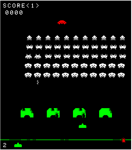
Game as it stands today
Although my implementation is playable, the following features have not been implemented:
high score
2nd player
extra life (referred to as "extended play" by Computer Archeology)
sounds for flying saucers
attract mode
Here is the CODEPEN of the code as it is today. As I look back and write this new blog series, I might change the code.


Comments